
 Français


_11zon.webp)


_14_11zon.webp)
_6_11zon.webp)



Artificial Intelligence and 3D Scanning: The Future of Weld Inspection?
- LAURENT DAROLT
- 05 Nov, 2026
- News and innovations
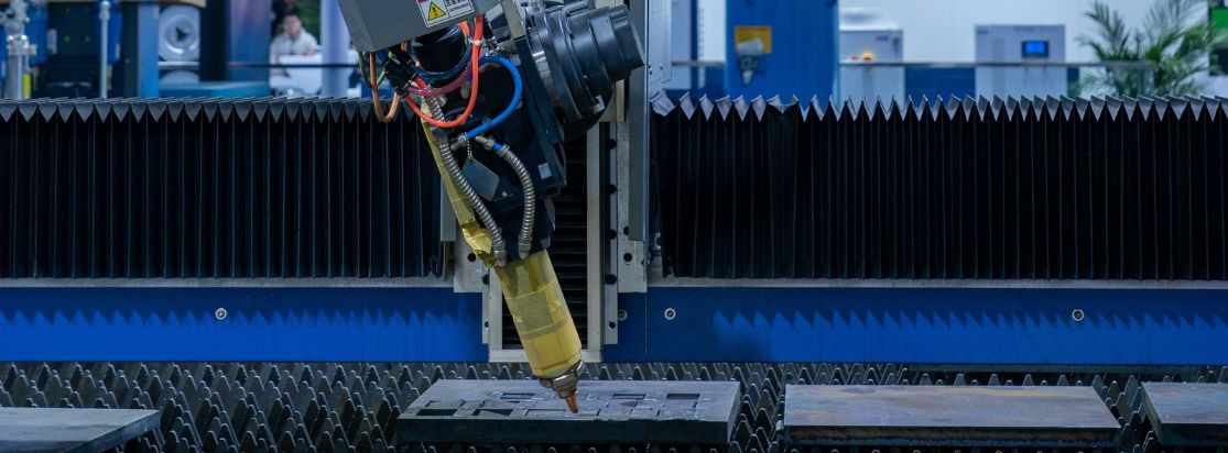
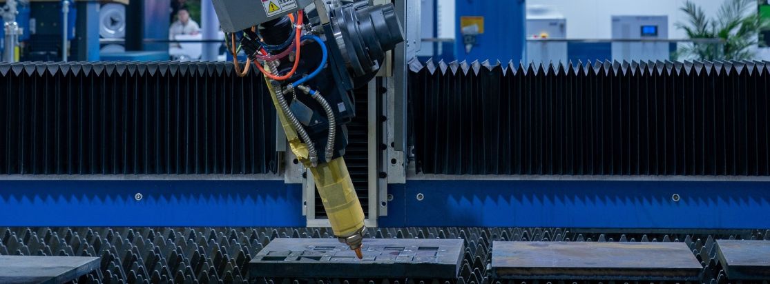
3D scanning is a non-contact optical measurement technique that projects a laser line or point to obtain the spatial coordinates of an object. It enables precise measurement of the external geometry of a weld bead. Artificial intelligence, meanwhile, assists inspectors by rapidly analysing these profiles or inspection signals to identify anomalies. These technologies speed up component inspection on production lines. However, an optical sensor cannot detect defects located inside the metal. Furthermore, detection algorithms can produce errors if lighting conditions or surface characteristics change in the workshop. Validation by a certified human expert therefore remains essential to ensure that welded joints comply with regulatory requirements.
Key Takeaways
- Surface scanning: 3D scanning digitises the external geometry of a weld without touching or damaging the component.
- Rapid preliminary analysis: Artificial intelligence automatically identifies suspicious areas, saving inspection teams valuable time.
- Limited to external surfaces: Optical scanners cannot detect internal defects such as porosity or lack of fusion.
- AI sensitivity: Variations in lighting, digital noise or image blur can lead to inaccurate algorithmic assessments.
- Human responsibility: An inspector qualified in accordance with ISO 9712 remains responsible for validating the final inspection results and assessing compliance.
How Do 3D Scanning and Artificial Intelligence Work?
The modernisation of industrial inspection relies on three distinct stages that must be considered separately. Physical data acquisition records the exact shape of the component using an optical sensor. Mathematical analysis then processes these measurements using specialised software. Finally, the ultimate decision rests exclusively with the person responsible for quality assurance.
3D Scanning Converts Surface Geometry into Measurements
3D scanning works by sweeping a laser beam across a metal surface to calculate distances without any physical contact. This optical measurement generates a point cloud, a collection of three-dimensional coordinates describing the exact geometry of the weld bead.
A 3D laser profilometer can record data with a very fine measurement spacing of 0.07 mm between points. This scanning process reconstructs an accurate surface profile using optical triangulation. It enables the assessment of local geometry at the weld toe, including the transition radius and weld angle. These two parameters directly influence the fatigue resistance of mechanical structures.
Raw laser measurement data often contain digital noise caused by metallic reflections or vibrations. It is therefore essential to apply digital filters, such as Gaussian or low-pass filters, to smooth the profile without distorting the actual geometry. This accurate acquisition of the real surface profile complements engineering processes such as numerical welding simulation, which predicts joint deformation before manufacturing.
AI Identifies Suspicious Patterns and Signals
Artificial intelligence comes into play immediately after digitisation to automatically identify manufacturing anomalies. It relies on an algorithm, a sequence of automated computer instructions that performs complex calculations.
To operate, the system must first be provided with training data. These data consist of reference images or signals used to train the artificial neural network. The neural network compares measured 3D profiles, radiographic images or ultrasonic signals with the examples it has learned during training. The system immediately alerts the inspector to areas showing geometric deviations or suspicious signals.
This software provides only a preliminary screening alert. In the absence of a standard specifically certifying AI for this application, the decision to accept or reject a component remains the responsibility of a human inspector qualified in accordance with ISO 9712.
Understanding these operating principles makes it easier to assess the actual capabilities of these technologies when dealing with defects encountered in the workshop.
What Defects Can These Technologies Detect?
To ensure effective quality control, the person responsible must select the inspection method best suited to the location of the defect. A surface imperfection cannot be detected using the same tools as a cavity hidden deep inside the metal. Furthermore, the presence of a measured imperfection does not automatically mean that the component must be rejected.
Surface Dimensions and Visible Imperfections Measured in 3D
3D scanning directly measures the visible geometric features on the external surface of welded joints. The system automatically calculates weld bead width, height and convexity, as well as undercut depth and plate misalignment.
These continuous optical measurements can replace conventional manual inspections performed using mechanical measuring instruments such as the Cam Gauge welding gauge or the Hi-Lo Gauge. Manual gauges provide isolated measurements at specific points. In contrast, a 3D scanner can inspect the entire length of a welded joint without leaving areas unchecked.
Visual inspection procedures are governed by ISO 17637. The tolerance limits and quality levels for measured weld imperfections are specified in ISO 5817.
Internal Defects Analysed Using Appropriate NDT Methods
To inspect the interior of a metal component, inspectors must use NDT (Non-Destructive Testing), which encompasses methods used to assess the integrity of a component without damaging or destroying it. ISO 17635 establishes the general rules for selecting the appropriate non-destructive testing method according to the material and type of welded joint.
An optical 3D scanner cannot detect anomalies located inside the material. It cannot identify internal porosity, slag inclusions, internal cracks or lack of fusion. To analyse these hidden defects, artificial intelligence must be combined with inspection technologies capable of examining the interior of the material, such as digital X-ray radiography or ultrasonic testing. This combination of technologies helps assess welding defects and acceptance criteria required by applicable standards and regulations.
| Technology | Data Collected | What It Reveals | Main Limitation | Role of the Inspector |
|---|---|---|---|---|
| 3D Laser Scanning | Point cloud | External geometry, weld toe radius and angle, undercuts | Cannot detect internal volumetric defects | Validates the settings and confirms the measurements |
| Radiographic Testing + AI | Digital X-ray images | Internal porosity, inclusions, gas cavities | Requires specialised equipment and radiation protection measures | Interprets alerts generated by AI |
| Ultrasonic Testing + AI | Acoustic signals | Internal cracks, lack of fusion | Requires adequate acoustic coupling with the surface | Assesses the severity of internal defects |
| Manual Visual Inspection | Direct observation | Major surface defects | Discontinuous and repetitive measurements | Performs the inspection and determines the quality level |
Once the detection capabilities have been clarified, it is important to examine how these technologies can be integrated directly into the production environment.
What Are the Advantages and Limitations in the Workshop?
Inspection automation addresses the need to increase industrial production rates. However, implementing these new software solutions requires striking the right balance between improving productivity and controlling manufacturing risks.
Improving Speed, Consistency and Traceability
Automated systems can inspect components much faster than manual visual inspection. Measurements are no longer affected by operator fatigue, ensuring objective and repeatable assessments across different shifts.
These technologies significantly improve traceability, meaning the ability to maintain a complete digital history of inspections and measurements performed on each component. Each digitised profile generates a computer file that is permanently stored in the factory's database. These advanced systems complement the range of modern weld inspection tools used in automated manufacturing facilities.
Managing Data, Errors and Human Validation
Real-world manufacturing environments present complex physical disturbances that can affect sensors. Dust, oil, variations in lighting and reflections from metal surfaces can interfere with optical imaging.
To obtain accurate profile measurements, mathematical filters such as Gaussian or low-pass filters must be applied to reduce digital noise. An industrial study published in April 2023 by CEA-List as part of the Confiance.ai programme evaluated the AIMOS tool (AI Metamorphism Observing Software). The tests were conducted using a Renault manufacturing use case involving the inspection of photographs of welds on vehicle rear axles. Researchers demonstrated that reduced brightness or image blur could alter AI-generated inspection results.
It is therefore important to distinguish between research-stage technology, laboratory demonstrators and commercially available software. To date, no international standard provides a framework for certifying an AI algorithm to automatically approve a weld without human inspection.
Understanding these technical constraints helps establish a clear assessment of whether investing in these technologies is appropriate.
Conclusion
The introduction of algorithms and advanced data processing is transforming the daily work of quality control teams. Inspectors can now rely on software tools capable of processing thousands of geometric measurements per second.
The Key Takeaway
3D scanning and artificial intelligence do not replace human inspectors. Instead, they act as rapid inspection assistants, helping to screen components and identify surface geometry anomalies or suspicious signals. Legal responsibility for confirming the conformity of a welded joint remains with the inspector certified in accordance with ISO 9712.
Recommended Next Steps
Before purchasing 3D scanning equipment or AI-based analysis software, quality managers should prepare detailed technical specifications. These should identify the most common types of defects, establish the required measurement accuracy in millimetres and verify the ISO standards specified by their customers.
Sources Used
- CEA-List / Confiance.ai Study (19 April 2023) – AIMOS (AI Metamorphism Observing Software) tested for assessing weld conformity on Renault vehicle rear axles.
- Research by Renken et al. (2024), Applications in Engineering Science – Calibration of Gaussian and low-pass filters on 3D laser profiles with a measurement spacing of 0.07 mm, and evaluation of weld toe geometry (radius and angle).
- ISO 17635 – General rules for non-destructive testing of welded joints.
- ISO 17637 – Visual testing of fusion-welded joints.
- ISO 5817 – Quality levels for imperfections in welded joints.
- ISO 9712 – Qualification and certification of non-destructive testing (NDT) personnel.