
 Français



_11zon.webp)


_14_11zon.webp)
_6_11zon.webp)



MIG/MAG Settings: Complete Tables for Mild Steel, Stainless Steel and Aluminium
- LAURENT DAROLT
- 22 Sep, 2026
- Welding techniques
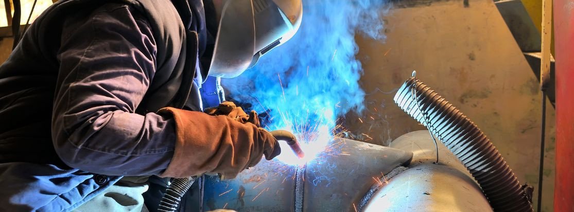
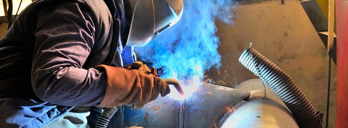
MIG/MAG welding parameters depend on a precise configuration of metal type, material thickness, wire diameter, shielding gas, joint geometry, and welding position. While modern power sources offer pre-set synergic programmes, these serve only as a baseline. Professional operators must manually validate arc characteristics on a test coupon to account for machine-specific calibration and environmental variables.
Five key points to remember
- The 50A/mm Rule : For mild steel, start with 50 Amps for every 1 mm of plate thickness.
- Gas Flow Ratio: Calculate shielding gas flow (LPM) by multiplying wire diameter (mm) by 10.
- CTWD Limit: Keep the Contact-to-Work Distance (stickout) within 1.25 cm (1/2 inch) to prevent porosity.
- Current Control: In GMAW processes, the wire-feed speed is the primary controller of amperage.
- Oxide Removal: Aluminium requires mechanical cleaning with a dedicated stainless steel brush before welding to remove the oxide layer.
HOW CAN RELIABLE MIG/MAG SETTINGS BE ESTABLISHED?
The strategic management of parameter synergy is the foundation of structural integrity. The relationship between voltage and amperage determines arc stability and the melting rate of the electrode. Without a balanced synchronisation between these variables, the process risks instability, excessive spatter, or insufficient penetration.
Relating thickness, wire diameter, wire-feed speed, current and voltage
These four variables are intrinsically linked. In the MIG/MAG process, the wire-feed speed directly dictates the amperage (current). Use the "50 Amps per mm" rule as a primary reference for mild steel. As plate thickness increases, this factor decreases—dropping to 40A or 30A per mm—to manage the higher heat input and maintain control of the weld pool. Higher voltage settings are necessary for thicker sections and larger wire diameters to ensure the arc has sufficient energy to fuse the base metal.
Adapting gas, polarity, transfer mode and CTWD
External factors dictate arc stability and shielding efficiency. Standard gas flow follows the "Diameter x 10" rule (e.g., 10 LPM for 1.0 mm wire). The Contact-to-Work Distance (CTWD) must not exceed 1.25 cm (1/2 inch) to maintain a laminar gas shield. For industrial applications, using high-quality MIG/MAG welding equipment is essential for maintaining these tight tolerances during high-duty cycles.
General parameters must be refined into material-specific starting points to ensure metallurgical compliance.
WHICH MIG/MAG STARTING-SETTING TABLES SHOULD BE USED?
Standardised tables allow professional workshops to maintain consistency. However, these figures require machine-specific validation, as different power sources possess unique synergic lines and arc characteristics.
Mild steel: starting settings
Standard mild steel (MAG) requires an Argon/CO2 mix for optimal arc stability. Using high-quality MIG/MAG wire spools ensures consistent deoxidation of the weld pool.
| Thickness (mm) |
Wire (mm) |
Gas / Flow Rate (L/min) |
Wire Feed Speed (m/min) |
Voltage (V) |
Current (A) |
Transfer Mode |
|---|---|---|---|---|---|---|
| 1.5 | 0.8 | Ar + CO₂ / 8–10 | 4.5–5.5 | 16–17 | 75 | Short-circuit |
| 2.0 | 0.8 | Ar + CO₂ / 10–12 | 6.5–7.5 | 18–19 | 100 | Short-circuit |
| 3.0 | 1.0 | Ar + CO₂ / 10–12 | 5.5–6.5 | 19–21 | 150 | Short-circuit |
| 5.0 | 1.0 | Ar + CO₂ / 10–12 | 8.5–10.0 | 24–26 | 200 | Spray transfer |
| 10.0 | 1.2 | Ar + CO₂ / 12–14 | 7.0–8.5 | 28–30 | 300 | Spray transfer |
*Note: Wire-feed speed (m/min) varies by machine; validate against synergic lines. Technical validation required before publication.
The use of ER70S-6 SG2 steel wire is standard for achieving optimal bead appearance on carbon steels.
Stainless steel: starting settings
Stainless steel utilizes active gas (Argon/CO2), typically with lower CO2 levels (1-3%) to prevent carbon pickup and maintain corrosion resistance.
| Thickness | Wire Type | Gas / Flow | Wire-feed Speed | Voltage | Indicative Current | Polarity |
|---|---|---|---|---|---|---|
| 1.5 mm | ER308L | Ar/CO₂ / 8 LPM | Validate* | Low | 70–80 A | DCEP |
| 1.5 mm | ER316L | Ar/CO₂ / 8 LPM | Validate* | Low | 70–80 A | DCEP |
| 3.0 mm | ER308L | Ar/CO₂ / 10 LPM | Validate* | Mid | 140–150 A | DCEP |
| 3.0 mm | ER316L | Ar/CO₂ / 10 LPM | Validate* | Mid | 140–150 A | DCEP |
For 304L or 308L alloys, ER308LSi wire for 304L/308L is recommended for improved pool fluidity due to its silicon content.
Aluminium: starting settings
MIG welding of aluminium requires 100% Pure Argon. Due to high thermal conductivity, thicknesses above 4 mm require a pre-heat of 65–95°C to ensure adequate penetration.
| Thickness | Wire Type | Gas / Flow | Equipment | Voltage | Current | Polarity |
|---|---|---|---|---|---|---|
| 2.0 mm | 4043/5356 | 100% Ar / 12 LPM | Spool/Push-Pull | Validate* | 100–120 A | DCEP |
| 4.0 mm | 4043/5356 | 100% Ar / 15 LPM | Spool/Push-Pull | Validate* | 180–200 A | DCEP |
| 6.0 mm | 5356 | 100% Ar / 15 LPM | Spool/Push-Pull | Validate* | 220 A+ | DCEP |
When using soft aluminium wire, MIG/MAG welding machines must be paired with push-pull torches or spool guns to prevent bird-nesting. High-strength ER5356 aluminium wire is the industry standard for marine and structural applications.
Establishing base parameters is the first step; real-time fine-tuning is required to correct emerging defects.
HOW SHOULD SETTINGS BE FINE-TUNED AND DEFECTS CORRECTED?
Reading the arc and the resulting bead geometry is critical for proactive quality control. Auditory and visual cues provide immediate feedback on whether the arc is "cold" or "hot."
Reading the arc and bead to correct voltage and wire feed
- Concave Beads: Commonly found in vertical-down welding due to gravity. If found in flat positions, it indicates voltage is too high, wire-feed is too slow, or travel speed is excessive.
- Convex (Ropey) Beads: This profile indicates the settings are "too cold." Insufficient voltage prevents the weld pool from wetting out at the toes, leading to poor fusion and potential structural failure.
Correcting porosity, spatter, lack of fusion and feeding faults
Maintaining MIG/MAG torches and consumables prevents the majority of common defects.
| Symptom | Possible Causes | Checks | Correction |
|---|---|---|---|
| Porosity | Excessive torch angle; dirty metal; gas leaks; drafts. | Check torch angle; inspect for surface oil/oxide; check hose seals. | Maintain 0–15° angle; clean metal with SS brush; increase gas flow (max 15 LPM). |
| Excessive Spatter | Voltage too low; CTWD too long; contaminated wire. | Verify voltage/wire speed ratio; check stickout length. | Increase voltage; shorten CTWD to < 1.25 cm; replace rusty or oily wire. |
| Lack of Fusion | Incorrect torch angle; fast travel; low heat input. | Inspect angle (keep 0–15°); check arc position on pool edge. | Reduce travel speed; increase voltage or wire-feed speed. |
| Feeding Faults | Worn contact tip; wrong liner; drive roll tension. | Inspect tip for bore wear; check liner material (PTFE/Nylon for Al). | Replace tip/nozzle; use PTFE/Nylon for Al; clean nozzle of spatter. |
Ensure the earth connection is close to the weld zone and that the contact tip size matches the wire diameter exactly to avoid arc hunting.
Successful MIG/MAG welding relies on a continuous loop of setting, validation, and real-time adjustment. By applying the 50A/mm baseline and strictly managing gas coverage and CTWD, operators ensure the structural integrity of the final joint.
The answer to remember
Professional welding performance is achieved through the synergy of machine parameters, rigorous testing on coupons, and the ability to interpret bead geometry to make precise adjustments.
The recommended next step
Audit your consumables inventory and establish a replacement schedule for contact tips (every 10-15 arc hours) to ensure consistent arc performance. Consider synergic power sources with Bluetooth capability for faster, error-free parameter transfer.
Sources Used:
- Fronius International GmbH: Setting the MIG/MAG Installation (50A/mm rule).
- Miller Electric Mfg. LLC: Troubleshooting Common MIG Weld Defects (Torch angle, porosity).
- ESAB France: Guide for Welding Aluminium (Pre-heating, 100% Argon).
- ESAB: Torch Maintenance & Consumable Lifecycle.