
 Français


_11zon.webp)


_14_11zon.webp)
_6_11zon.webp)



Residual Stresses and Distortion After Welding
- LAURENT DAROLT
- 15 Oct, 2026
- Welding techniques
During the assembly of metal components, localized heating followed by cooling causes the metal to expand and then contract unevenly. Shrinkage refers to the natural contraction of the material as it cools. If the metal's natural movement is restricted by the structure or fixtures, residual stresses remain. Residual stress is a permanent internal stress locked within the material. Under the influence of these internal forces, the component undergoes geometric changes and becomes distorted.
Several factors influence the extent of this phenomenon, including the type of material, sheet thickness, joint type, volume of deposited weld metal, heat input, number of passes, fit-up quality, and degree of restraint. Restraint refers to the rigid mechanical holding of components during the operation.
To control the assembly process, deviations should be prevented from the design stage. The volume of weld metal should be limited to what is strictly necessary to meet mechanical requirements. Weld beads should also be balanced on either side of the neutral axis.
The team must prepare the assembly, apply an appropriate welding sequence, check dimensions according to the inspection plan, and implement an approved corrective method if deviations occur.
Two major technical limitations must be kept in mind. First, rigid restraint reduces geometric distortion but increases the level of internal residual stresses. Second, heat treatment reduces these internal stresses but does not automatically straighten a distorted component.
Key Takeaways
- Physical cause: Localized thermal expansion and contraction generate internal stresses and permanent plastic deformation of the metal.
- Design considerations: Minimize the volume of deposited weld metal and balance weld bead positions relative to the neutral axis of the component.
- Assembly practices: Use angular presetting, the back-step welding technique, and alternating welding sequences to distribute heat input evenly.
- Restraint trade-off: Mechanical restraint limits external geometric distortion but increases the overall level of internal residual stresses.
- Corrective methods: Mechanical or thermal straightening using wedge-shaped heat shrinking requires strict temperature control, with temperatures limited to between 600°C and 650°C for carbon-manganese (C-Mn) steel.
Why Does Welding Cause Residual Stresses and Distortion?
Understanding the thermomechanical mechanisms of welding is a major strategic concern for fabrication workshops, helping prevent the costly rejection of complex structures.
Understanding the Differences Between Thermal Expansion, Shrinkage, Distortion, and Residual Stress
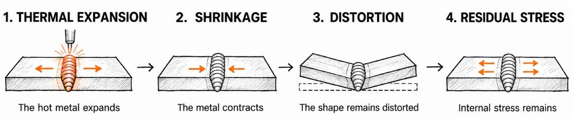
The final distortion of a welded structure differs from the material's simple local thermal response because it is permanent. When the arc is initiated, concentrated heating rapidly raises the temperature of the weld pool. This temperature increase causes localized expansion of the molten metal and the heat-affected zone. The surrounding cold metal immediately restricts this expansion. This restraint generates compressive stress and plastic deformation at elevated temperatures. During cooling, the solid metal contracts. In carbon-manganese steel, the volume reduction of the molten weld pool reaches approximately 3% during solidification. An additional contraction of 7% then occurs as the temperature decreases to ambient conditions. This restrained shrinkage generates internal tensile stresses. When these stresses exceed the material's yield strength, the deformation becomes permanent. Thermal expansion refers to the temporary increase in volume caused by heat. Shrinkage is the contraction of metal during cooling. Geometric distortion is the visible change in the shape of the component. Residual stress refers to the internal mechanical stress that remains within the structure after it has completely cooled.
Identifying Types of Welding Distortion and Contributing Factors
The types of geometric distortion observed in fabrication workshops include longitudinal shrinkage, transverse shrinkage, angular distortion, bending, buckling, warping, and twisting. Longitudinal shrinkage shortens the component parallel to the weld bead. Transverse shrinkage reduces the width of the component perpendicular to the joint. Angular distortion causes the components to rotate around the weld axis due to asymmetrical contraction through the material thickness. Bending occurs when the weld centerline is offset from the neutral axis, causing curvature along the length of the component. Buckling and warping affect thin metal sheets subjected to high compressive stresses over large areas caused by shrinkage. Twisting occurs when a closed structure undergoes torsional deformation due to shear stresses at its corners. Material properties significantly influence the extent of these phenomena. For example, stainless steel has a higher coefficient of thermal expansion than carbon steel, increasing its tendency to distort. Excessive heat input also enlarges the heated zone and increases shrinkage.
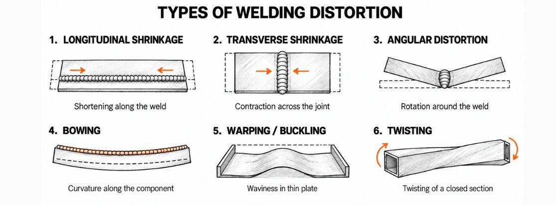
| Phénomène | Aspect visuel | Causes principales | Mode de contrôle / Prévention |
|---|---|---|---|
| Longitudinal / Transverse Shrinkage | Overall shortening of the component | Weld bead contraction during cooling | Initial oversizing, reduction of deposited weld metal volume |
| Angular Distortion | Rotation of flanges or plates around the joint | Asymmetrical contraction through the material thickness (e.g., single-V groove) | Angular presetting, double-V (X) groove, balanced weld beads |
| Warping / Buckling | Waviness in thin sheet metal or plates | Compressive stresses generated by shrinkage | Use of stiffeners, balanced distribution of heat input |
| Bending (Bowing) | Curvature of the component along its length | Weld positioned away from the neutral axis | Positioning weld beads along the neutral axis, alternating weld sequences |
| Twisting | Torsional deformation of a closed structure (e.g., box section) | Shear deformation caused by uneven thermal expansion | Increasing the number of tack welds, assembly fixturing and clamping |
A precise understanding of these thermal mechanisms makes it possible to develop effective preventive measures from the initial design and assembly stages.
How Can Welding Distortion Be Prevented?
From an economic perspective, preventing welding distortion during the design and assembly stages is significantly more cost-effective than carrying out expensive repairs afterward.
Optimizing Design, Fit-Up, and Weld Metal Volume
To limit thermal movement, the primary rule is to minimize the amount of deposited weld metal and strategically position the joints. Eliminating unnecessary welded connections is the first line of defense. Using bent plates or rolled sections can eliminate numerous weld beads and remove the very source of distortion. When welding is essential, groove geometry plays a decisive role. On thick components, a symmetrical double-V (X) groove reduces the volume of deposited weld metal by half compared with a single-V groove. This joint preparation balances shrinkage forces on either side of the neutral axis. In addition, overwelding must be avoided. Excessive fillet weld throat thickness does not increase the required mechanical strength but unnecessarily increases distortion. To anticipate the behavior of complex structures before fabrication, engineers use numerical welding simulation. Finally, the accuracy of the initial fit-up determines the final result. Using professional welding tables ensures a perfectly flat reference surface. For pipe welding, using pipe alignment clamps ensures a consistent root gap and prevents variations in heat input.
Controlling Tack Welding, Restraint, Heat Input, and Welding Sequence
Applying practical workshop techniques helps distribute heat input and limit movement during welding. Alternating welding sequences should be prioritized to balance forces on both sides of the neutral axis. The back-step welding technique involves depositing short weld beads in the direction opposite to the overall progression of the joint. This method divides the heating process into smaller sections and reduces overall longitudinal shrinkage. Angular presetting also provides an effective solution. It involves positioning components at an initial angle opposite to the expected distortion before welding, allowing shrinkage to bring the structure into the desired geometry. Mechanical restraint is another commonly used method. Using clamps, fixtures, or stiffeners prevents geometric movement of the assembly. However, restraint limits external distortion at the expense of increased internal residual stresses. Reducing heat input offers an additional approach. The use of pulsed MIG/MAG welding provides precise control over metal transfer and reduces shrinkage. To securely hold components in place before assembly, the technical team must understand how to use welding clamps. Installing the complete assembly on a welding table with an S355 steel tabletop provides the rigidity needed to hold components securely. Nevertheless, reducing heat input must never compromise weld penetration, fusion, or compliance with the qualified Welding Procedure Specification (WPS).
Even when all preventive measures are rigorously applied, a final dimensional inspection remains essential to confirm that the component meets the required specifications.
How to Inspect and Correct a Component After Welding?
Geometric quality control ensures manufacturing compliance, while correcting any deviations requires the application of strictly qualified procedures.
Measuring Geometry and Determining Acceptability
Component inspection must establish a fundamental distinction between measuring external dimensional deviations and evaluating internal residual stresses. Dimensional inspection is performed using geometric measuring instruments, straightedges, or angle gauges. The measured values are compared with the tolerances specified in the fabrication drawings or applicable construction code. ISO 13920 establishes general tolerances for welded structures. However, this standard applies only when explicitly referenced in the engineering drawings or contract. Information to be verified or validated before publication.
Choosing Between Mechanical Straightening, Thermal Straightening, and Heat Treatment
When geometric tolerances are exceeded, the workshop must choose between mechanical straightening, thermal straightening, and stress-relief heat treatment.
Mechanical straightening involves applying an external force using a press or hydraulic jacks. The principle consists of deforming the component in the opposite direction beyond its yield strength. This plastic deformation compensates for elastic recovery (spring-back). This method carries risks of work hardening, surface indentation, and crack initiation if excessive force is applied.
Thermal straightening (also known as heat shrinking) relies on creating a localized heated zone. The hot metal attempts to expand but is restrained by the surrounding cold metal. As a result, it undergoes plastic deformation under compression. During cooling, the heated zone contracts and generates a tensile force that pulls the component back toward its intended geometry. Heating can be applied using spot, line, or wedge-shaped patterns. Wedge heating is suitable for structural sections and thick assemblies. The length of the wedge should equal two-thirds of the plate width. The base of the triangle should measure one-sixth of this length. The operator must heat from the apex toward the base while ensuring uniform heat distribution through the material thickness. For carbon-manganese steel, the heating temperature must be strictly limited to between 600°C and 650°C (dark red heat). Exceeding 650°C may alter the metallurgical structure and affect the material's mechanical properties.
Post-weld heat treatment (PWHT), also known as stress-relief heat treatment, involves heating the entire structure in a temperature-controlled furnace. This process reduces the level of internal residual stresses. However, while heat treatment reduces internal stresses, it does not automatically straighten a distorted component.
| Situation / Défaut observé | Méthode de contrôle | Action corrective possible | Risques associés à maîtriser |
|---|---|---|---|
| Thin Sheet Metal Warping | Dimensional flatness inspection | Localized spot heating on the convex side | Excessive localized shrinkage, thermal surface marks |
| Angular Distortion of a Flange | Angle measurement using a protractor | Line heat shrinking on the side opposite the weld bead | Metal overheating, metallurgical alterations |
| Bending / Bowing of a Structural Section | Straightness inspection using a straightedge | Progressive mechanical pressing with shims to compensate for spring-back | Excessive work hardening, risk of instability |
| Overall Assembly Distortion | Complete geometric inspection against the fabrication drawings | Wedge heating from the apex toward the base | Exceeding the 650°C temperature limit, cracking |
Controlling geometric distortion requires continuous monitoring throughout the entire manufacturing process, from design to final inspection.
Controlling Post-Weld Distortion: An Operational Summary
Quality assurance of welded assemblies relies on an integrated approach to optimizing productivity and ensuring manufacturing compliance.
Key Takeaways
Post-weld distortion results from the unavoidable succession of uneven thermal cycles within the material. Effective distortion control is based on three key principles: optimizing joint geometry and weld metal volume during the design stage, planning welding sequences and restraint methods during assembly, and rigorously applying approved thermal or mechanical straightening techniques.
Recommended Next Steps
Workshop managers and welding engineers should formalize their recommendations by reviewing their Welding Procedure Specifications (WPS). It is also advisable to assess whether the available clamping and fixturing equipment is suitable for the intended applications. Finally, teams must have their thermal straightening procedures validated by a welding engineering specialist before performing any corrective work on structural components.
Sources and References
- TWI - Job Knowledge: "Distortion - Types and Causes" (F.033)
- TWI - Job Knowledge: "Distortion - Prevention by Design" (F.034)
- TWI - Job Knowledge: "Distortion Control - Prevention by Fabrication Techniques" (F.036)
- TWI - Job Knowledge: "Distortion - Corrective Techniques" (F.037)
- Federal Highway Administration (FHWA): "Demonstration Project on Heat-Straightening Repair of Damaged Steel Bridge Members" (Report No. FHWA-IF-99-004)