
 Français



_11zon.webp)


_14_11zon.webp)
_6_11zon.webp)



Welding Defects in MIG/MAG, TIG & MMA
- LAURENT DAROLT
- 13 Oct, 2026
- Welding techniques
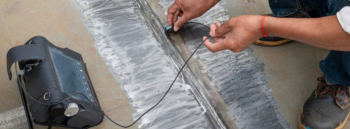
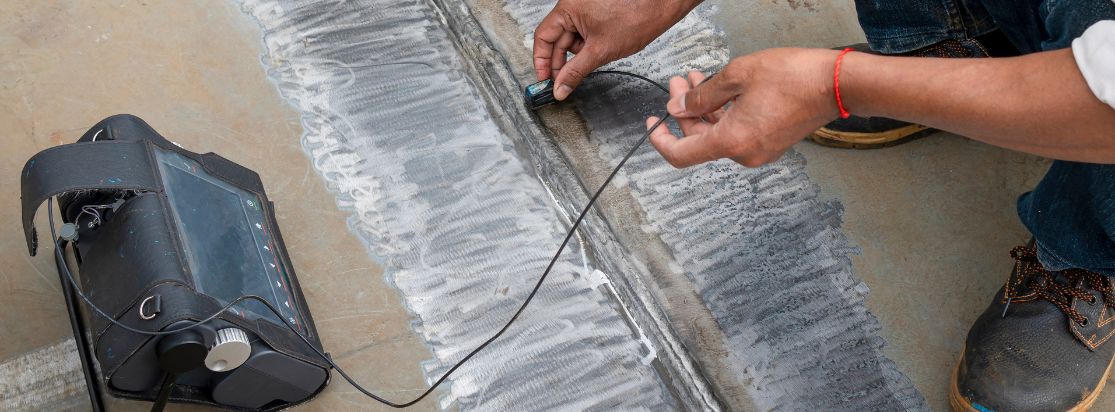
A systematic diagnosis of a welded joint begins with a visual examination of surface symptoms. It continues with verification of the base metal, joint preparation, and welding position. The inspection then covers the shielding gas or coated electrode, electrical settings, welding technique, and equipment condition. Imperfections are classified according to ISO 6520-1. Compliance requires a direct comparison with the Welding Procedure Specification (WPS) and the acceptance criteria defined in ISO 5817 for steel, nickel, and titanium, or ISO 10042 for aluminium. Visual inspection is limited to the surface. Assessing the internal integrity of the joint requires Non-Destructive Testing (NDT). A photograph alone can never serve as proof of technical acceptability.
Key Takeaways
- Always distinguish between an acceptable imperfection and a critical defect according to the applicable standards (ISO 5817 / ISO 10042).
- Strictly follow the complete visual inspection sequence before adjusting the welding machine settings.
- Identify the root cause related to the welding process (shielding gas, wire feeding, tungsten electrode, or electrode coating) before attempting any corrective action.
- Recognise that workpiece cleanliness and moisture control are essential factors in preventing porosity and inclusions.
- Never repair a critical defect or crack without an approved repair procedure (WPS).
How to Properly Diagnose a Welding Defect
A systematic diagnostic approach in the workshop directly impacts the profitability of metal fabrication. Unstructured equipment adjustments lead to considerable time wasted on grinding and rework, while reducing the consistency and repeatability of industrial welding quality.
Inspect the Weld Bead and Record Welding Conditions
Visual inspection requires a rigorous 11-step procedure:
- Safety: Check the welder's personal protective equipment (PPE) and ensure the work area is safe.
- Visual appearance: Examine the overall weld bead geometry, uniformity, and surface discoloration.
- Base material and joint: Check edge cleanliness, bevel preparation, root gap, and workpiece alignment.
- Electrical parameters: Record welding current, arc voltage, and travel speed. To maintain stable welding parameters, it is essential to use suitable welding machines.
- Consumables: Identify the type and condition of the welding wire, tungsten electrode, or coated electrode.
- Shielding gas: Verify the shielding gas composition, the flow rate measured at the nozzle, and the overall integrity of the gas hoses and connections.
- Polarity: Check the electrical connections (Direct Current Electrode Negative – DCEN, Direct Current Electrode Positive – DCEP, or Alternating Current – AC).
- Work clamp: Inspect the quality of the electrical contact and the positioning of the work return cable.
- Welding technique: Evaluate the torch angle, travel speed, arc length, and wire stick-out.
- Equipment: Check the condition of the torch, drive roll wear, wire liner, and electrical connections.
- WPS: Strictly compare the recorded welding parameters with the requirements specified in the Welding Procedure Specification (WPS).
Distinguishing Between Imperfections, Defects, and Acceptance Criteria
A welding imperfection refers to a discontinuity in the weld structure or a deviation from the intended weld geometry. An imperfection becomes a defect when its size or frequency exceeds the limits permitted by the applicable quality acceptance criteria. The welded joint is then considered non-compliant.
ISO 17637 specifies the requirements for visual testing of fusion-welded joints. When surface inspection alone cannot assess the internal integrity of the weld, ISO 17635 provides guidance on selecting additional Non-Destructive Testing (NDT) methods. These specialised techniques help evaluate weld integrity:
- Penetrant testing (PT): Uses coloured or fluorescent liquid penetrants to reveal surface-breaking discontinuities.
- Magnetic particle testing (MT): Detects surface and near-surface discontinuities in ferromagnetic materials using magnetic fields.
- Ultrasonic testing (UT): Uses reflected ultrasonic waves to detect and locate internal discontinuities.
- Radiographic testing (RT): Uses X-rays or gamma rays to detect internal discontinuities, including cavities and porosity.
A systematic inspection process enables the targeted identification of the most significant welding defects encountered in metal fabrication.
Which Welding Defects Should Be Checked First?
Early detection of discontinuities in deposited weld metal is essential for ensuring the mechanical integrity and safety of metal structures. Thorough inspection helps prevent serious structural failures when welded equipment is placed into service.
Porosity, Inclusions, and Cracks
Porosity occurs when gases become trapped in the weld pool during solidification. Gases such as hydrogen, nitrogen, or water vapour can form bubbles that remain trapped in the solidifying weld metal instead of escaping to the
| Symptom or Indicator | Welding Processes | Possible Causes | Systematic Inspection Steps | Documented Corrective Action | Decision or Additional Inspection |
|---|---|---|---|---|---|
| Internal or Surface-Breaking Porosity | MIG/MAG, TIG, MMA | Contaminated shielding gas, incorrect gas flow rate, moisture, draughts. |
|
Adjust the shielding gas flow rate (15–20 cfh for TIG as a general guideline), dry the joint and degrease the workpiece. | Penetrant testing for surface-breaking porosity or radiographic testing for internal defects, according to the applicable requirements. |
| Crater Cracks or Linear Cracks | MIG/MAG, TIG, MMA | Rapid weld pool cooling, residual stresses and excessive welding current. |
|
Enable the downslope function if available and add filler metal at the end of the weld pass. | Stop welding and assess the defect. Perform appropriate NDT according to the procedure and applicable requirements. |
| Slag Inclusions | MMA | Inadequate interpass cleaning, excessively convex weld bead profile, improper welding technique. |
|
Grind down excessively convex weld passes and thoroughly remove slag between successive passes. | Radiographic or ultrasonic testing according to the applicable quality requirements. |
| Lack of Fusion or Incomplete Penetration | MIG/MAG, TIG, MMA | Excessive arc length, excessive travel speed, incorrect torch or electrode angle, insufficient heat input. |
|
Correct the arc length, reduce travel speed, adjust welding current and joint preparation. | Ultrasonic or radiographic testing depending on the type of defect being investigated. |
| Undercut Along the Weld Toe | MIG/MAG, TIG, MMA | Excessive welding current, excessive travel speed, incorrect weaving technique. |
|
Reduce welding current, decrease travel speed, and allow sufficient dwell time at the weld edges. | Visual and dimensional inspection using a weld gauge. |
| Weld Overlap | MIG/MAG, TIG, MMA | Travel speed too slow, incorrect torch or electrode angle, unsuitable arc parameters. |
|
Increase travel speed and adjust welding parameters according to the process used. | Visual inspection and removal of the defect through appropriate repair procedures if necessary. |
| Burn-Through of the Base Metal | MIG/MAG, TIG, MMA | Excessive welding current, excessive root gap, travel speed too slow. |
|
Reduce welding current, increase travel speed and correct the root gap. | Remove the burn-through area and carry out repairs according to the applicable procedure. |
| Excessively Concave or Convex Weld Profile | MIG/MAG, TIG, MMA | Incorrect voltage or current settings, electrode coating type, improper welding technique. |
|
Adjust welding parameters and travel speed to achieve a weld profile that meets the joint requirements. | Visual inspection using a weld reinforcement height gauge. |
| Excessive Weld Spatter | MIG/MAG, MMA | Incorrect voltage settings in short-circuit transfer, excessive arc length. |
|
Adjust voltage and wire feed speed in MIG/MAG welding. Shorten the arc in MMA welding. | Mechanical cleaning by scraping if permitted. |
| Structural Distortion | MIG/MAG, TIG, MMA | Excessive heat input, insufficient clamping, poorly planned welding sequence. |
|
Control welding heat input, adjust travel speed and weld pass sequence, and apply appropriate clamping. | Dimensional inspection of the welded assembly. |
Identifying welding defects leads to a more detailed examination of the technical characteristics specific to each welding machine and process.
What Are the Specific Causes of Defects in Each Welding Process?
Each welding technology has its own physical variables. Controlling these parameters can help prevent 80% of recurring welding imperfections observed in workshops.
MIG/MAG: Shielding Gas, Wire Feeding, Stick-Out, and Settings
To diagnose defects in this welding process, follow the "Check First / Correct Afterwards" approach.
It is important to distinguish between a visible weld defect (porosity, undercut) and a malfunction of a welding machine component (wire feeding problems, drive roll slippage). Choosing reliable MIG/MAG welding equipment helps prevent many operational issues. The shielding gas flow rate must be precisely adjusted according to the nozzle diameter. Excessive gas flow creates turbulence. This turbulence draws surrounding air into the shielding gas stream, contaminating the weld pool and causing porosity. Air entering through a damaged gas hose produces the same effect.
The distance between the contact tip and the workpiece (stick-out, or free wire length) directly influences welding current. Excessive stick-out reduces penetration and destabilises the arc. Voltage and wire feed speed settings determine the metal transfer mode:
- Short-circuit transfer: Metal droplets are transferred through direct contact between the wire and the weld pool.
- Spray transfer: Fine metal droplets are continuously transferred across the arc at high welding currents.
Incorrect voltage settings during short-circuit transfer can cause excessive weld spatter. It is also essential to regularly inspect MIG/MAG welding torches and consumable parts to ensure smooth and consistent wire feeding.
TIG: Tungsten Electrode, Gas Shielding, Polarity, and Crater Formation
The "Check First / Correct Afterwards" approach also applies to TIG welding.
Proper tungsten electrode preparation is essential for arc stability. Excessive electrode-positive (EP) polarity causes a large ball to form at the electrode tip, reducing arc precision. Direct contact between the tungsten electrode and the molten weld pool can introduce tungsten inclusions into the weld. Gas shielding requires pure argon, with a recommended flow rate of 15 to 20 cfh (cubic feet per hour), or an argon/helium mixture for welding thick aluminium sections. Argon/CO2 mixtures (commonly used in MIG/MAG welding) must never be used for TIG welding because they cause immediate and severe tungsten contamination.
On TIG welding machines, direct current electrode negative (DCEN) is used for welding steel. Alternating current (AC) is used for aluminium welding to break down the aluminium oxide layer (alumina). AC balance controls the proportion of electrode-positive (EP) cleaning time relative to electrode-negative (EN) penetration time. Insufficient cleaning action can leave black particles in the weld pool. Excessive cleaning action causes the tungsten electrode tip to become excessively rounded. The nozzle fitted to TIG welding torches should also be inspected to maintain a stable, laminar shielding gas flow.
At the end of a weld bead, abruptly cutting off the welding current causes rapid cooling. The resulting contraction can lead to crater cracking. Using the current downslope or crater control function (a gradual, programmed reduction in welding current at the end of the weld) allows the crater to be filled progressively. When welding stainless steel, the absence of shielding gas on the reverse side of the joint causes oxidation known as sugaring. At high temperatures, chromium reacts with oxygen in the surrounding air, resulting in the formation of chromium oxides. This local depletion of available chromium permanently compromises the metal's passive protective layer and its corrosion resistance.
MMA: Slag, Arc Length, Electrode Angle, and Moisture
Diagnosing shielded metal arc welding (MMA/SMAW) defects also follows the "Check First / Correct Afterwards" approach.
Slag inclusions occur when electrode coating residues become trapped beneath the molten weld metal. The level of risk varies according to the composition of the electrode coating:
- Basic electrodes: These electrodes contain high proportions of calcium carbonate and fluorspar, helping to reduce oxygen content and weld pool surface tension. They naturally produce a convex weld bead and highly adherent slag, increasing the risk of slag inclusions compared with rutile-coated electrodes.
- Rutile electrodes: These electrodes are based on titanium dioxide and generally produce a more concave weld bead profile with slag that is easier to remove.
To ensure welding quality when using MMA/ARC welding equipment, the electrode angle should be between 45° and 90° relative to the electrode holder axis to provide comfortable handling and good control of metal transfer. Excessive arc length increases arc voltage and causes spatter. Moisture absorbed by the electrode coating generates water vapour during welding. This vapour releases hydrogen into the molten weld metal, causing porosity and increasing the risk of hydrogen-induced cold cracking. Proper storage of welding electrodes in a dry environment, or appropriate electrode baking before use, helps eliminate this source of contamination.
This detailed analysis provides the basis for a clear diagnostic procedure and establishes the decision-making criteria for stopping welding operations when necessary.
Conclusion
Implementing a structured welding defect diagnosis process improves the reliability of the industrial B2B production chain. It helps ensure compliance with applicable welding standards while controlling production costs.
Key Steps in the Welding Defect Diagnosis Process
The inspection process is based on four sequential actions:
- Observation: Conduct a complete visual examination of the weld bead and systematically record the welding conditions in the workshop.
- ISO Classification: Accurately classify the discontinuity according to ISO 6520-1 and assess its acceptability against ISO 5817 / ISO 10042.
- Root Cause Analysis: Examine process-specific variables, including shielding gas, consumables, electrical parameters, and welding technique.
- Correction: Adjust welding parameters or correct the welding technique based on manufacturer specifications and the Welding Procedure Specification (WPS).
When to Stop Welding and Request an Inspection
The welder must immediately stop welding operations in the following situations:
- A crack appears, regardless of its length or location.
- A recurring defect persists after an initial adjustment of the welding parameters.
- The recorded welding parameters clearly deviate from the ranges specified in the Welding Procedure Specification (WPS).
In these critical situations, a welding coordinator or Non-Destructive Testing (NDT) inspector must be consulted. To prevent non-conformities, always validate your technical welding procedures and refer to the manufacturer's instructions for welding equipment and consumables.