
 Français



_11zon.webp)


_14_11zon.webp)
_6_11zon.webp)



Welding Symbols: How to Read Them Correctly on a Drawing
- LAURENT DAROLT
- 08 Oct, 2026
- Welding techniques
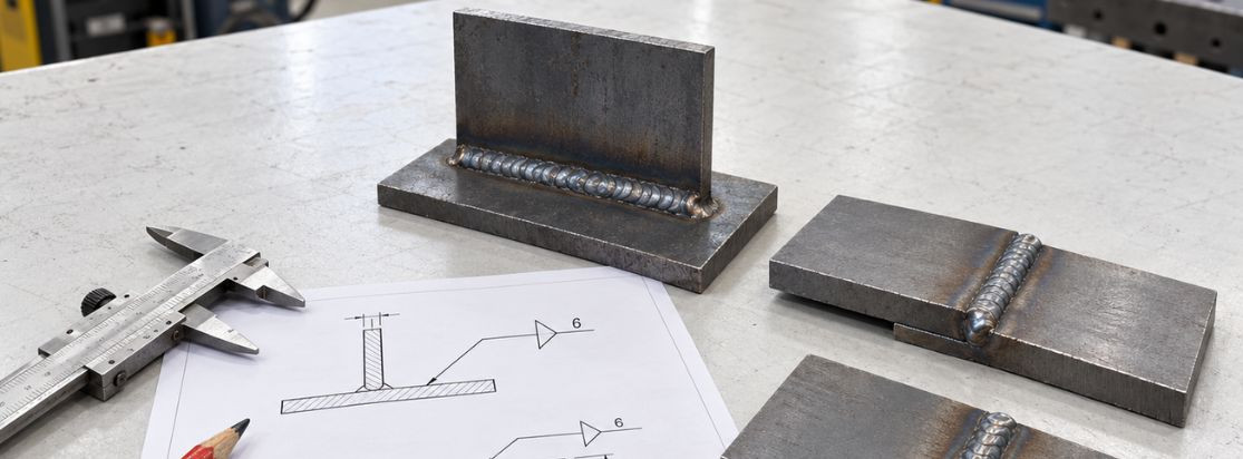
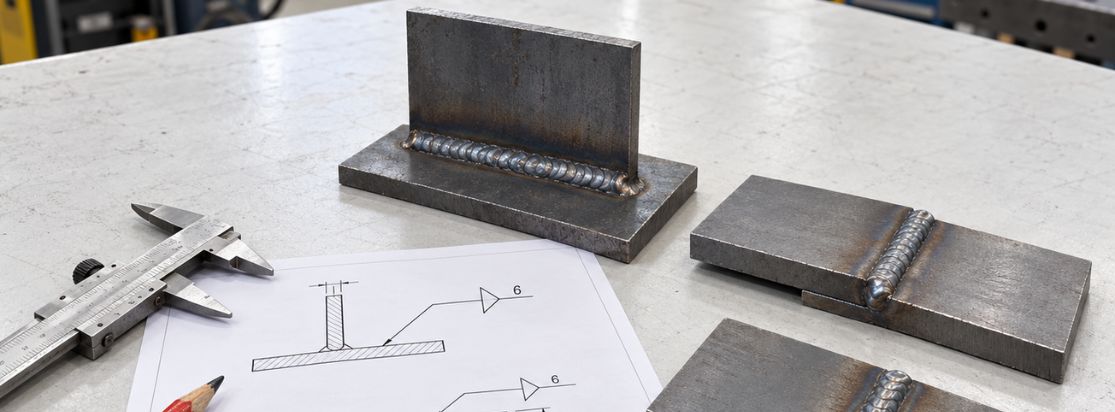
To determine where to weld, which type of weld to perform, and which dimensions to follow on a technical drawing, you need to follow a step-by-step method. First, check the standard and representation system specified in the title block, which contains the drawing's general information. Next, identify the joint to be welded, as indicated by the arrow. Use the horizontal reference line to determine which side requires welding. For example, the arrow-side weld symbol is positioned below this line. Identify the type of weld to be performed using the graphical symbol placed on the reference line. Then, read the numerical values specifying the weld size, length, or spacing. After that, interpret the supplementary symbols and any information provided in the tail of the welding symbol, which is located at the end opposite the arrow. Finally, check the legend, general notes, and WPS (Welding Procedure Specification), which defines the requirements for executing the weld. If any ambiguity remains on the drawing, it must always be clarified with the engineering or design department rather than being left to interpretation.
Key Takeaways
- Title block verification: Check the representation system (A or B) specified in the drawing's title block.
- Joint identification: Follow the arrow to precisely locate the joint to be welded.
- Reference line interpretation: Determine whether the weld is required on the arrow side or the other side.
- Dimension analysis: Read the dimensions (throat thickness, length) indicated around the welding symbol.
- WPS validation: Verify that the welding process and workshop parameters comply with the Welding Procedure Specification (WPS) before striking the arc.
How to Read a Welding Symbol Step by Step
Reading welding symbols systematically ensures that welded components meet technical requirements and helps prevent costly fabrication errors in the workshop. The structure of the welding symbol provides welders with an essential visual guide for positioning and executing each weld bead according to engineering specifications.
Identify the Arrow, Reference Line, and Tail
To read a welding symbol, you must first identify the arrow, reference line, and tail. The arrow points directly to the joint that needs to be welded. The horizontal reference line contains all the graphical and numerical instructions for the weld.
The tail is located at the opposite end of the reference line from the arrow and contains additional information, such as the welding process, quality level, or Welding Procedure Specification (WPS) reference. To carry out these operations accurately, it is essential to select welding machines suited to the welding process and the specific requirements of the job.
Identify the Arrow Side, Other Side, or Both Sides
To determine which side of a joint requires welding, you must examine the position of the welding symbol in relation to the reference line. The arrow side refers to the side of the joint indicated by the arrowhead, while the other side refers to the opposite side of the joint. The NF EN ISO 2553 standard defines two distinct representation systems:
- System A (based on ISO 2553): This system uses two reference lines: one continuous line and one dashed line. The position of the welding symbol relative to the continuous or dashed reference line determines which side of the joint must be welded.
- System B (based on AWS A2.4): This system uses a single reference line. Welding symbols placed below the line indicate the arrow side, while those positioned above the line indicate the other side.
System A, System B, and AWS welding symbol conventions must not be mixed within the same technical drawing.
| Symbol Description | Meaning | Value Type (a, z, s) | Practical Example |
|---|---|---|---|
| Fillet Weld Notation a | Required Throat Thickness | Value a | a5 (5 mm throat thickness) |
| Fillet Weld Notation z | Fillet Weld Leg Length | Value z | z7 (7 mm leg length) |
| Effective Penetration s | Effective Penetration Depth | Value s | s8 (8 mm penetration depth) |
| Intermittent Weld | Weld Length and Centre-to-Centre Spacing | Length - Pitch | 50-100 (50 mm weld length, 100 mm pitch) |
| Concave Weld | Concave Weld Surface Profile | Weld Profile | Concave Contour Symbol |
Once the weld location has been identified on the joint, the next step is to analyze the geometric shape of the weld and its exact dimensions.
How to Identify Weld Types and Their Dimensions
Correctly interpreting the welding symbol and its specified dimensions is essential to the mechanical strength of the structure. Accurate weld dimensions help ensure that the joint can withstand the intended loads without premature failure.
Identify Common Weld Types
To identify common weld types, you must examine the graphical symbol displayed on the reference line. Basic welding symbols represent the most common configurations: fillet weld, square groove weld, V-groove weld, single-bevel groove weld, double-V groove weld, U-groove weld, J-groove weld, plug weld, and spot weld.
Three physical characteristics must be distinguished on a technical drawing. Joint preparation refers to the bevel or groove machined into the components before welding. The required deposited weld metal represents the filler metal added to form the joint. Finally, the finished weld contour defines the surface shape, which may be convex, concave, or flat. The selected weld profile directly influences stress concentration and fatigue resistance under dynamic loading. A smooth concave profile can reduce stress concentration, while excessive convexity may create a notch effect that increases the risk of cracking.
Understanding a, z, s, Weld Length, and Pitch
To understand weld dimensions, you must interpret the letters a, z, and s, along with the numerical values associated with the welding symbol. For a fillet weld, the letter a indicates the throat thickness, the letter z represents the leg length, and the letter s specifies the effective penetration depth.
Longitudinal dimensions define the extent of the weld. The weld length is indicated to the right of the welding symbol. For an intermittent weld, the notation separates the length of each weld segment from the pitch (centre-to-centre spacing) using a hyphen.
| Symbol Description | Meaning | Value Type (a, z, s) | Practical Example |
|---|---|---|---|
| Fillet Weld Notation a | Required Throat Thickness | Value a | a5 (5 mm throat thickness) |
| Fillet Weld Notation z | Fillet Weld Leg Length | Value z | z7 (7 mm leg length) |
| Effective Penetration s | Effective Penetration Depth | Value s | s8 (8 mm effective penetration) |
| Intermittent Weld | Weld Segment Length and Centre-to-Centre Spacing | Length - Pitch | 50-100 (50 mm segment, 100 mm pitch) |
| Concave Weld | Concave Weld Surface Profile | Weld Profile | Concave Contour Symbol |
A thorough understanding of weld dimensions allows the necessary operational checks to be carried out before starting the welding process.
How to Avoid Misinterpreting a Welding Drawing
Misinterpreting a welding drawing can lead to serious operational risks, including internal weld defects, non-compliance with the Welding Procedure Specification (WPS), and health hazards for operators. It is therefore essential to verify the welding process, welding position, and supplementary symbols before striking the arc.
Understanding Welding Processes, Positions, and Supplementary Symbols
To interpret the welding process, welding position, and supplementary symbols, you must examine the tail of the welding symbol and the graphical annotations on the reference line. Welding process identification numbers are defined by the ISO 4063 standard:
- Process 111: The number 111 refers to manual metal arc welding with covered electrodes (MMA/SMAW) (Information to be verified or validated before publication). This process requires suitable ARC/MMA welding equipment, such as the EWM Pico 160 ARC welding machine.
- Process 135: The number 135 refers to MAG welding with a solid wire electrode. This process is performed using reliable MIG/MAG welding equipment, such as the GYS SMARTMIG 162 MIG/MAG welding machine.
- Process 141: The number 141 refers to TIG welding. This process requires precise TIG welding equipment, such as the EWM Picotig 220 TIG welding machine.
Standardized welding positions defined by ISO 6947 (such as PA, PB, and PF) specify the orientation of the weld during welding (Information to be verified or validated before publication). Supplementary symbols provide additional welding instructions: a circle at the junction of the arrow and reference line indicates a weld all around the joint, a flag indicates a field weld, and a specific contour symbol defines the required weld profile. Keep two essential rules in mind: the arrow never indicates the direction of welding travel, and the graphical welding symbol does not specify the welding machine's electrical settings.
Checking the Welding Drawing Before Starting
Before welding, the welder must systematically cross-check the information on the technical drawing against the Welding Procedure Specification (WPS). This comparison helps prevent errors. For example, it confirms that an actual welding heat input of 4.1 kJ/cm remains below the 6 kJ/cm limit specified in the WPS. This verification also helps identify the required non-destructive testing (NDT) methods, such as liquid penetrant testing for surface-breaking defects and radiographic testing for internal defects, while ensuring safe working conditions during operations in confined spaces.
- Identify the standard and representation system: Check the drawing's title block to determine whether System A or System B is used.
- Verify the joint location: Confirm the exact joint indicated by the arrow.
- Confirm the ISO 4063 welding process: Ensure that the welding machine and consumables correspond to the specified process number.
- Check the weld dimensions: Verify the throat thickness (a), leg length (z), effective penetration (s), and weld length.
- Consult the WPS: Check the welding current, shielding gas flow rate, and environmental safety requirements, particularly for confined-space welding.
- Clarify any uncertainties: Contact the technical supervisor or engineering department if any information on the drawing is unclear.
Consistently applying these verification steps helps maintain high welding quality standards and ensures safer production operations.
Conclusion
Mastering the interpretation of welding symbols is essential for compliant, safe, and traceable industrial fabrication. It connects the engineering department's technical requirements with the practical demands of workshop operations.
Key Takeaways
Knowing how to read a welding drawing is essential for ensuring the quality, compliance, and safety of every welded metal assembly. This skill relies on a systematic analysis method, a clear understanding of the differences between representation Systems A and B, and proper document traceability between the technical drawing and the Welding Procedure Specification (WPS).
What to Do Before Starting
Before beginning any welding or assembly work, carefully prepare your workstation and check all relevant welding documentation. To protect your operators and ensure that your fabricated components meet industrial standards, equip your workshop with welding equipment that complies with applicable requirements, or consult a welding engineering specialist to validate your welding procedures.